Introduction
The SAE J1939 is standard from the Society of Automotive Engineers (SAE) used to define recommended practice for communication and diagnostics among vehicle ECUs. Initially the standard had focus only on heavy-duty truck then leveraged to tractors, buses and industrial machineries. It specifies standard process for how ECUs should exchange data between them. Hence it creates common language between ECUs in a vehicle to collect, process and share data. This makes modules of vehicle can be received from any supplier who follows the standard without worrying about incompatibility.
Initially CAN standard was not included in J1939 and used double or triple 8 bit addresses for exchange. From the year 2000, (CAN) ISO 11898 has been included. Among the five layers defined by J1939, Controller Area Network(CAN) ISO 11898 becomes two layers namely physical layer (uses only 29 bit “extended identifier) and data link layer. The session and presentation layers are not part of specification.
J1939 modules operates at fixed 250 kb/sec, exchanges packets with DLC of 8 and unique identifiers which contain an index called Parameter Group Number (PGN). The PGN plays major role to identify function of the message and associated data. The J1939 defines PGN for not only a wide range of automotive parameters but also agricultural, marine and off – road vehicles. The data defined by PGN is created by collection of SPN which represent unique parameters of associated vehicle.
The data driven higher level protocol SAE J1939 provides improved network management which includes address claiming, unlimited data length and node address, But those are absent in CAN. The standard uses 29 bit identifier supported in CAN 2.0B to encode PGN. The PGN is unique number assigned for collection of parameter for example parameter group “engine temp” which includes temperature of coolant, fuel and oil. The collection of PGN for various vehicle parameters are defined in roughly 379 page document called SAE J1939/71. The standard also allows using manufacturer-specific parameter groups.
29 bit identifier of CAN packet is divided into following fields

- 3 bit priority - Priority of the packet
- 18 bit PGN - Parameter Group Number
- 8 bit Source Address – Source address of node transmitting the message
18 bit PGN is divided into following fields

- 1 bit reserved
- 1 data page (Current value of data page is 0 because all PGN for data page 0 not yet filled)
- 8 bit PDU format
- 8 bit PDU specific
- Transmission Rate: 1 sec
- Data Length: 8 bytes
- Default Priority: 6 L
- PG Number: 65262 (FEEEhex)
- Byte 1: Engine Coolant Temperature – SPN 110
- Byte 2: Fuel Temperature – SPN 174
- Byte 3, 4: Engine Oil Temperature – SPN 175
- Byte 5, 6: Turbocharger Oil Temperature- SPN 176
- Byte 7: Engine Intercooler Temperature - SPN 52
- Byte 8: Engine Intercooler Thermostat Opening - SPN 1134
- Arbitrary address bit
- Industry group, length 3 bits
- Vehicle system instance, length 4 bits
- Vehicle system, length 7 bits
- Reserved bit
- Function, length 8 bits
- Function instance, length 5 bits
- ECU instance, length 3 bits
- Manufacturer code, length 11 bits
- Identity number, length 21 bits
PDU format decides whether exchange is peer to peer or broadcasting If value of PDU format is < 240 then the message is peer to peer else if PDU format is >=240 the message is broadcasting. When PDU format is < 240 PDU specific is used to encode destination node address. Though the PDU format is <240 and setting PDU Specific to 255 is considered as broadcasting. Hence no ECU in the network can posses this address.
Example
PGN 65262 - Engine Temperature
Description of Data
Suspect Parameter Numbers (SPN)
The term Suspect Parameter Number (SPN) designates a particular parameter that is part of a Parameter Group Number (PGN). In addition to providing details about the data related to that parameter, such as its type, length, and scaling, SPNs are used to identify the cause of a diagnostic problem code (DTC).
| DP | PGN Range(hex) | Number of PGN | SAE/MF | Communication |
|---|---|---|---|---|
| 0 | 000000-00EE00 | 239 | SAE | PDU1 - Peer to Peer |
| 0 | 00EF00 | 1 | MF | PDU1 - Peer to Peer |
| 0 | 00F000-00FEFF | 3840 | SAE | PDU2 - Broadcast |
| 0 | 00FF00-00FFFF | 256 | MF | PDU2 - Broadcast |
Controller Application (CA)
Every electronic control unit (ECU) has a software program operating in it; this program is known as the Controller Application, or CA. A single physical ECU may be home to several CAs. To interact over a J1939 network, the CA needs to have a unique address and associated device name, as per SAE J1939 regulations.
CA Address
This source address appears in every communication that this CA sends. A total of 255 addresses are conceivable. Valid addresses range from 0 to 253. The network address 255, sometimes referred to as the global address, is used for broadcasting messages and is only allowed in the J1939 message identifier's Destination Address field. It is never allowed in the Source Address field. The network address 254, sometimes referred to as the NULL address, is only allowed in the J1939 message identifier's Source Address field and is only meant to be used in Network Management communications. Different CAs determine the source address in different ways. The CAs are divided into two groups for address claim purposes: single address capable and arbitrary address capable.
NAME
Every CA needs to be able to supply its own 64-bit NAME. A NAME and the source address are included in the address claim message. This message is used to link a specific network source address to a NAME. In addition to providing a functional description, the NAME also provides a numerical value that can be utilized in address arbitration.
The NAME is composed of 10 fields
The structure of NAME is shown in below Address Claim message
| Arbittory Address capable | Industry Group | Vehicle System instant | Vehicle System | Reserved | Function | Function Instance | ECU Instance | Manufacture Code | Identity Number | |||
|---|---|---|---|---|---|---|---|---|---|---|---|---|
| 1 bit | 3 bits | 4 bits | 7 bits | 1 bit | 8 bits | 5 bits | 3 bits | 8 bits | 3 bits | 5 bits | 8 bits | 8 bits |
| byte 8 | byte 7 | byte 6 | byte 5 | byte 4 | byte 3 | byte 2 | byte 1 | |||||
Arbitrary Address Capable
This one-bit parameter indicates whether or not the CA can be used as an arbitrary field. Address claim conflicts are resolved with its help. When this bit is set to 1, the CA will choose an address from the range of 128 to 247 in order to settle the address conflict with the one whose NAME has a greater priority (lower numeric value).
Industry Group
The committee defines and assigns a 3-bit field called Industry Group. The Industry Group field finds NAMEs related to a certain industry that employs SAE J1939, such as Agricultural Equipment or On-Highway Equipment.
Vehicle System Instance
A 4-bit field called Vehicle System Instance is used to identify a specific instance of a given Vehicle System in a network that is connected.
Vehicle System Field
The committee created and assigned the 7-bit Vehicle System field, which can be connected to a common name when paired with the Industry Group.
Reserved Field
Awaiting SAE's future definition. Zero should be set for the reserved bit.
Function Field
The committee defines and assigns the function, which is an 8-bit field. The SAE J1939 standard pre-assigns the lower function values between 0 and 127. The definition of a function is independent of any other field when its values fall between 0 and 127. Function values above 127 depend on the vehicle system and industrial group. Function determines a common name for a particular controller when paired with the Industry Group and Vehicle System fields.
Function Instance Field
A 5-bit field called the Function Instance indicates the specific instance of a Function on the same Vehicle System inside a network.
ECU Instance Field
A 3-bit field called "ECU Instance" designates which of a set of electronic control modules linked to a specific function is being referred to.
Manufacturer Code
An 11-bit column called the Manufacturer Code identifies the business that produced the electronic control module that this NAME is referring to. The SAE J1939 basic document contains the committee-assigned manufacturer codes.
Identity Number Field
The ECU manufacturer assigns the Identity Number, a 21-bit field, to the name. In situations when the NAME might not be unique otherwise, the Identity Number is required. It should be a distinct field that remains constant when power is removed.
How Does J1939 Communication Works?
J1939 uses concept of node addressing. Hence each CA should have unique address. When CA boots up it acquires address via different methods. Based on the capability of acquiring address, they are divided into single address capable CA and arbitrary address capable CA. the single address capable CA is further divided in to non configurable, service configurable, command configurable and self configurable.
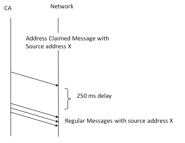
Single Address Capable CA With Non Configurable Source Address
Before sending any packets related to application each CA in the network should send an address claimed message with unique address after power on self test. This address is fixed and could not be changed. After delays of 250ms the CA will transmit its regular application messages. For example let us consider three CAs with following source addresses 0xE6,0x00 and 0x03. The startup traffic upon POST is as follows
   // PGN=EE00 SA=E6 DA=FF ACL
   0.000568 2  18EEFFE6x       Tx   d 8 69 34 A9 E8 00 83 00 10
   // PGN=EE00 SA=0 DA=FF ACL
   0.000568 1  18EEFF00x       Tx   d 8 4C 34 A9 E8 00 00 00 00
   // PGN=EE00 SA=3 DA=FF ACL
   0.001128 1  18EEFF03x       Tx   d 8 4E 34 A9 E8 00 03 00 00
Let us decode the first packet in this group. We can decode 0x18 EEFFE6 as follows
| 1 10 00 1110 1110 1111 1111 1110 0110 | |
|---|---|
| 110 | Priority (6) |
| 0 | Reserved |
| 0 | Data Page(0) |
| 1110 1110 – 0xEE (238) | PDU Format (< 240 hence peer to peer) |
| 1111 1111 – 0xFF (255) | Global Destination Address - (Broad Casting) |
| 1110 0110 – 0xE6 (230) | Source Address(0x230) |
| 0xEE00 | PGN For Address Claimed |
Hence data bytes of this message will be the name of the CA
| 69 34 A9 E8 00 83 00 10 | |||
|---|---|---|---|
| Binary | Hex | Description | |
| 0 0011 0000 0000 0001 0000 | 0x030010 | ID(21) | |
| 000 0000 0100 | 0x004 ( Manufacture Code) (11) | Dearborn Group Inc. | |
| 000 | 0x0 | ECU Instance (3) | |
| 1 1101 | 0x1D | Function Instance (5) | |
| 1010 1001 | 0xA9 | Function(8) | |
| 0 | 0 | Reserved (1) | |
| 001 1010 | 0x1A | Vehicle System (7) | |
| 1001 | 0x9 | Vehicle System Instant (4) | |
| 110 | 0x6 | Industry Group (3) | |
| 0 | 0 | Arbitrary Address Incapable (0) | |
After decoding the ID and packet data, we come to know that the packet is an address claimed message, The CA which transmit this packet can only have one source address that is not changeable. It does not follow any arbitrary address claim procedure. After 250ms, CA can transmit its regular message
Single Address Capable CA With Service Configurable Source Address
There is no difference in behavior from CA with non configurable source address except source address of CA can be changed using service tool or DIP switches in it.
Single Address Capable CA With Command Configurable Source Address
The the source address of a CA can be changed by means of commands. Following is the specification of command
| Commanded Address Message - PGN definition | |
|---|---|
| Transmission Rate | As Defined |
| Data Length | 9 |
| Data Page | 0 |
| PDU Format | 254 |
| PDU Specific | 216 |
| Default priority | 6 |
| Parameter Group Number | 65240(0x00FED8 |
| Source Address | |
| Name of the Commanded Address Destination | ||
|---|---|---|
| Byte 1 | Bits 8-1 | Least significant byte of the identity Number |
| Byte 2 | Bits 8-1 | Second byte of the identity Number |
| Byte 3 | Bits 5-1 | most significant byte of the identity Number |
| Bits 8-6 | Least significant 3 bits of manufacture code | |
| Byte 4 | Bits 8-1 | most significant bits of manufacture code |
| Byte 5 | Bits 8-4 | Function Instance |
| Bits 3-1 | ECU Instance | |
| Byte 6 | Bits 8-1 | Function |
| Byte 7 | Bits 8-2 | Vehicle System |
| Bit 1 | Reserved | |
| Byte 8 | Bit 8 | Arbitrary Address Capable |
| Bit 7-5 | Industry Group | |
| Bit 4-1 | Vehicle System Instance | |
| Byte 9 | Bit 8-1 | New Source Address (0-253) |
As this command has more than 8 byte, we have to use multi packet transmission. It uses two type of packets such as transport protocol connection management (TP.CM) and transport protocol data transfer (TP.DT). the TP.CM uses following packet structure
| Transport protocol – Connection Management – PGN definition | |
|---|---|
| PDU Specific | 255(Global Address) |
| Default Priority | 7 |
| Parameter Group Number | 0x00EC00 |
| Source Address | 0-253 |
| Transport protocol – Connection Management – Data fields | |
|---|---|
| Byte 1 | Control Byte =32(0x20) for BAM |
| Byte 2 | Message Size (Low byte) |
| Byte 3 | Message Size (High byte) |
| Byte 4 | Total Number of Packet |
| Byte 5 | Reserved=255(0xFF) |
| Byte 6 | Parameter Group Number (Low byte) |
| Byte 7 | Parameter Group Number (Middle byte) |
| Byte 8 | Parameter Group Number (High byte) |
The TP.DT uses following packet structure
| TP.DT PGN Definition | |
|---|---|
| Transmission rate | As required |
| Data Length | 8 |
| Data Page | 0 |
| PDU Format | 235 |
| PDU specific | 255(Global Address) |
| Default Priority | 7 |
| Paramter Group Number | 0x00EB00 |
| Source address | 0-253 |
| TP.DT - Data Field | |
| Byte1 | Sequence Number(1-255) |
| Byte2 | Data |
| Byte3 | Data |
| Byte4 | Data |
| Byte5 | Data |
| Byte6 | Data |
| Byte7 | Data |
| Byte8 | Data |
Let us consider we have network interconnection ECU or a service tool which has source address 0xE6. This CA wants to command ECU which claimed the source address 0x0 to use the address 0x3. To achieve that we have to use request and response as follows
   0.000560 2  18EEFF00x       Tx   d 8 4C 34 A9 E8 00 00 00 00  // PGN=EC00 SA=E6 DA=FF ACL
   0.000568 2  1CECFFE6x       Tx   d 8 20 09 00 02 FF D8 FE 00  // CA with source id 0xE6 commands CA with source id 0x0 to use the address 0x3
   0.000572 2  1CEBFFE6x       Tx   d 8 01 4C 34 A9 E8 00 00 00
   0.000585 2  1CEBFFE6x       Tx   d 8 02 00 03 FF FF FF FF FF
   0.000590 2  18EEFF03x       Tx   d 8 4C 34 A9 E8 00 00 00 00 // ACL with source address changed to 0x3

Arbitrary Address Capable CA
Arbitrary address capable CA uses address claim procedure to claim address. The process of exchanging messages and doing individual CA actions to administer the network collectively is known as the address claim method or network management procedure. Similar to other SAE J1939 communications, network management messages follow the same format. A network management message can only contain a null address in the source address field if it is a request for an Address Claimed or a Cannot Claim Address message. No response is received when a request is sent to the null address (254).
Let us consider arbitrary address capable CA want to claim an address. It initially queries other CAs in the network to transmit their claimed address using request message. Once it receives address of other CAs, it claimed an address that was not claimed and available to claim. To achieve that we have to use request and response as follows
   0.000560 1  18EAFFFEx       Tx   d 3 00 EE 00 00 00 00 00 00  // PGN=EA00 SA=0xFE DA=FF  Address Claim Message Request
   0.000562 1  18EEFFE6x       Tx   d 8 69 34 A9 E8 00 83 00 10  // PGN=EE00 SA=E6 DA=FF ACL
   0.000563 1  18EEFF00x       Tx   d 8 4C 34 A9 E8 00 00 00 00  // PGN=EE00 SA=0 DA=FF ACL
   0.000564 1  18EEFF03x       Tx   d 8 4E 34 A9 E8 00 03 00 00  // PGN=EE00 SA=3 DA=FF ACL
   0.000565 1  18EEFF04x       Tx   d 8 4D 34 A9 E8 00 03 00 00  // PGN=EA00 SA=0x04 DA=FF ACL

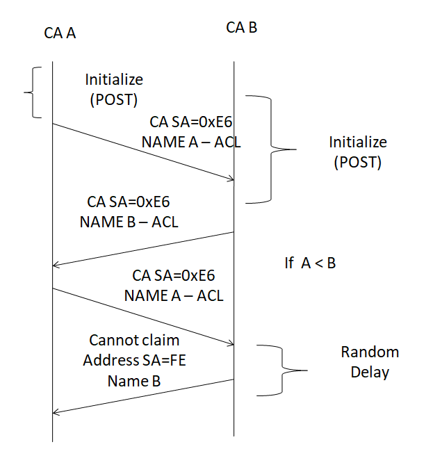
Let us consider a CA with the NAME B claims a source address which is used by another CA in the network with NAME A. The CA in the network will compare NAME of incoming CA. The NAME is considered as single 64 bit number and is compared with NAME of the CA in the network. If CA with name A has lower value (higher priority) than the CA with name B, then CA with NAME A transmit address claimed message again with same source address. After a while, CA with NAME B will transmit cannot claim message if it is arbitrary address incapable
   0.000563 1  18EEFFE6x       Tx   d 8 4C 34 A9 E8 00 00 00 00  // PGN=EE00 SA=E6 NAME A DA=FF ACL
   0.000575 1  18EEFFE6x       Tx   d 8 69 34 A9 E8 00 83 00 10  // PGN=EE00 SA=E6 NAME B DA=FF ACL
   0.000580 1  18EEFFE6x       Tx   d 8 4C 34 A9 E8 00 00 00 00  // PGN=EE00 SA=E6 NAME A DA=FF ACL A <B
   0.000590 1  18EEFFFEx       Tx   d 8 69 34 A9 E8 00 83 00 10  // PGN=EE00 SA=FE NAME B DA=FF Cannot claim address
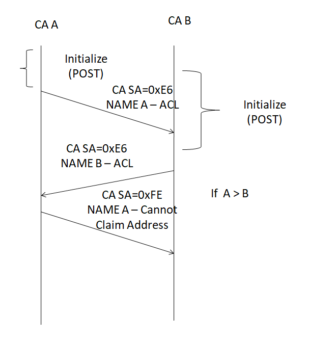
Let us consider another scenario in which Name A is greater than Name B (higher priority). Hence after a while CA A will send the cannot claim message if it is arbitrary address incapable
	0.000563 1  18EEFFE6x       Tx   d 8 69 34 A9 E8 00 00 00 00     // PGN=EE00 SA=E6 NAME A DA=FF ACL
	0.000575 1  18EEFFE6x       Tx   d 8 4C 34 A9 E8 00 83 00 10  	// PGN=EE00 SA=E6 NAME B DA=FF ACL
	0.000580 1  18EEFEE6x       Tx   d 8 69 34 A9 E8 00 00 00 00	// PGN=EE00 SA=FE NAME A DA=FF ACL A > B cannot claim address
Let us consider the scenario in which Name A is less than (Higher Priority) Name B. and Name B is arbitrary address capable then
   0.000563 1  18EEFFE6x       Tx   d 8 4C 34 A9 E8 00 00 00 00  // PGN=EE00 SA=E6 NAME A DA=FF ACL
   0.000575 1  18EEFFE6x       Tx   d 8 E9 34 A9 E8 00 83 00 10  // PGN=EE00 SA=E6 NAME B DA=FF ACL
   0.000580 1  18EEFFE6x       Tx   d 8 4C 34 A9 E8 00 00 00 00  // PGN=EE00 SA=E6 NAME A DA=FF ACL A < B
   0.000590 1  18EEFFE7x       Tx   d 8 E9 34 A9 E8 00 83 00 10  // PGN=EE00 SA=E7 NAME B DA=FF arbitrary address claim by CA with Name B
